Stoney,
could you please tell me more about the differences between the y-clark airfoil and the NACA23015 airfoils? The 109 is a y-clark, where the fw 190 is a NACA 23015. What properties do they exhibit, etc..
Well, I don't know so much about the Clark Y and I've never been able to find a lot of data about it. The 23000 series NACA airfoils, on the other hand, were the most prevalent and widely used airfoil in the history of aviation probably. Many of the WWII fighter aircraft in-game shared the 23000 series airfoils, or close variations.
The development of the 23000 series airfoil came out of the initial research of NACA (later to be known as NASA) and a lot of their wind tunnel testing in the 20's and 30's. As more and more planes switched from fabric (which didn't hold a true airfoil form in flight necessarily) to metal (which did), designers began to realize certain performance aspects of the airfoils could be improved. Now, remember that the Wright brothers had only flown 27 years prior to 1930, and a ton of the stuff we now know about aerodynamics was then still unknown. One aspect of airfoils that designers did know a lot about was the effect of increased camber on the pitching moment of airfoils. Camber is used to increase the Clmax of an airfoil, i.e. more camber = more lift given everything else the same. When camber goes up, the airfoil has a nose down pitching moment. When camber of some airfoils gets high enough to make the airfoil a very attractive choice from a lift perspective, it becomes a problem because a high enough nose-down pitching moment is introduced to create other problems.
This other problem is trim drag, or the drag created by the horizontal stabilizer counter-acting the nose down pitching moment of the wing. When the pitching moment goes up, the trim drag goes up. During this early period of airfoil design, minimizing pitching moment was seen as one of the most important characteristics of the airfoil chosen. NACA decided that if the airfoil was designed properly, pitching moment could be minimized. Their best result was the 23000 series of airfoils. It had very low profile drag, and a very low pitching moment compared to some of the other airfoils that had been used previously. As a result, it rapidly became the flavor of the month for airfoils, so-to-speak, and was widely accepted as a high-performance airfoil. As a result, it was used in almost all of the later model WWII fighter aircraft like the F4U, F6F, P-47, FW-190, (Lednicer also lists the Ki-48 and N1K2 and some of the Russian fighters like the La-5/7). The 23000 series can still be seen today in the Beechcraft Bonanza, and even in HiTech's RV-8, among others.
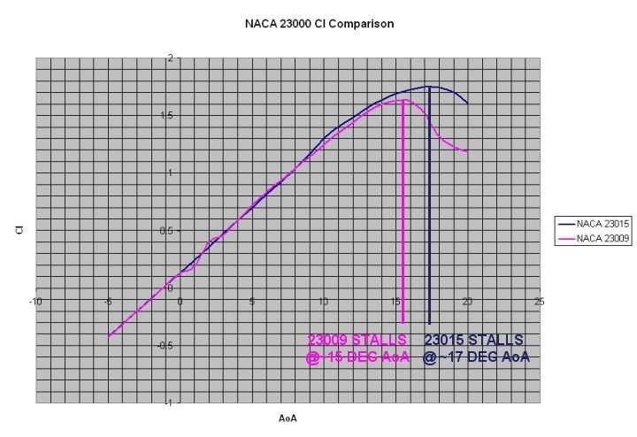
The problem is that (according to Harry Riblett) in changing the airfoil shape to minimize the pitching moment, NACA gave the 23000 series a very sharp leading edge profile on the top of the airfoil, and flattened the lower leading edge of the airfoil. This characteristic created a condition where, at the stall, airflow is disrupted further forward along the top edge of the airfoil than when compared to its contemporary airfoils. This created very sharp stall characteristics, which were even more pronounced when airfoil thicknesses were thinner (see graph below).
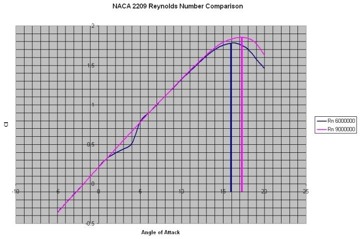
Now, typically, the Clmax of an airfoil increases with thickness. It also increases as the Reynolds number (a number that represents a relationship to the velocity X chord length of an airfoil) increases. These two images are plots I made on XFoil a few years ago. On the 23000 series comparison, you can see the impact of thickness on Clmax, and on the comparison of the 2200 series, you can see the impact of Reynolds number on Clmax.


Most WWII fighter aircraft used both planform taper (meaning that the wingtip had a shorter chord than the wing root) and also used thickness taper (meaning the wingtip had a thinner airfoil than the wing root). Given the graphs I posted above, you can see that they basically designed wings that were going to have a tendency to tip stall at high Angle of Attack conditions, i.e. the wing tip stalls while the wing root is still producing lift. At the same airspeed, the wing tip's thinner airfoil stalls sooner and more sharply, and the wing tip's lower reynold's number (since the wing tip chord is shorter than the wing root) is lower. The problem is that the ailerons, which control roll, are located on the wing tip. If you get into a tip stall condition, there will be insufficient flow over the ailerons to continue to control the aircraft in the roll axis. This is why when we stall fight aircraft in AH2, the planes want to roll over on their backs when we stall them, regardless of aileron input. All of the other resultant roll moments (engine torque being a large one since we're almost always at full power in a stall fight) have more force than what the ailerons can counteract.
Now, why would they design the wings this way? Lower drag, primarily, as profile drag decreases with airfoil thickness. Ignorance would be another reason. These guys were designing aircraft with nothing more than a plotting board and a slide rule. Much of what we no know from CFD analysis was unknown then. Also, they all thought, and many designers today still do think, that they could counteract all these tip stall tendencies with twist. Unfortunately, most of the time, all the twist did was add more drag, while still not providing enough of a difference to counteract the tip stall tendencies they designed in with their combination of airfoil thickness and planform taper. Ironically, the Me109, having been designed much earlier than some of its wartime counterparts, used leading edge slats to combat these tendencies, and were largely successful at controlling them. While I've not done the analysis in XFoil, I would assume that the Clark Y airfoil also had better stall characteristics than the 23000 series.
So, I don't know if I answered your question entirely, but hopefully this gives you a start on understanding some of the issues.