For many years it has driven me nuts how the standard pilot books describe pitch stability and CL/CG setups.
Like This which is very useful for a basic understanding.
Full page
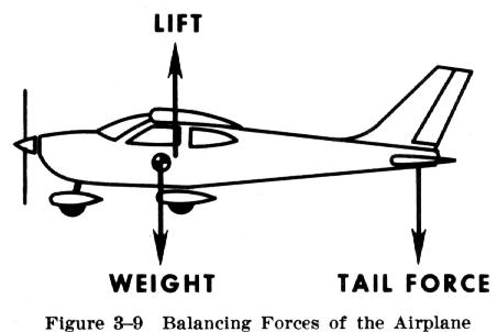
http://www.dauntless-soft.com/products/freebies/library/books/flt/chapter3/stability.htmThe diagram above would tend to make most people think plane would pitch down when loosing its horizontal tail planes.
But most fighter planes are set up like the following diagram, as are most plane when set up for fastest cruise.
Because you want both surfaces (wing and H stab) to be lifting, if the tail is pushing down the wing must push up the same amount to have static flight. And producing lift in either direction causes drag. In one case Wing + HStab = weight of plane. in the other (Wing = weight of plane + HSTAB lift) which creates more drag.

The entire page
http://en.wikipedia.org/wiki/Longitudinal_static_stabilityThe misconception comes from the definition of what is Center of lift. Is it the entire lifting surface of the wing and the tail plane, or just the wing.
So at last someone as posted a correct diagram and from and engineering perspective of pitch stability.
HiTech


