

Guns can destroy only what they can hit. This was a difficult problem for long-range gunnery against moving ships, which required the gun to place the shell where the ship would be when the shell arrived. At maximum battle range of about 28,000 yards (25,600m), a 16" (406mm) shell could take 40 seconds to reach the target, and a target steaming at 25 knots would have moved 560 yards (510m) while the shell was in flight. This was nearly twice the length of an Iowa-class battleship. Long-range fire control proved more difficult for naval engineers to perfect than the construction of guns capable of throwing shells to great distances. However, fire control advanced rapidly during the first part of the 20th century, and by 1939 fire control was one of the most sophisticated of naval technologies. The major naval powers closely guarded their fire control secrets, yet most fire control technology was derived from the British, and no one power had a decided advantage until the introduction of radar. Radar revolutionized fire control during the Pacific War and strongly favored the Allies.
Much of the impetus for developing long-range antiship gunnery came from the torpedo. Torpedoes could inflict massive damage, and it was felt that gunnery could compete with torpedoes only if guns could hit their targets from outside of torpedo range. The race between long-range gunnery and torpedoes reached its end point with the U.S. 16"/50 gun and the "Long Lance" torpedo; the 16" gun could theoretically hit a target at 42,000 yards (38,000 m) under perfect conditions, while the Long Lance had a maximum range of 48,000 yards (44,000 m) at its slowest speed setting (though this was rarely used.)
Antiship Fire Control
Small guns with limited range used simple telescopic sights. The gunner made his best guess at the range, set the elevation accordingly, put his cross hairs on the target, and kept them centered as his own ship rolled (continuous aim). Opinions differed on which was the best point in the ship's roll to fire, but most gunners tried to fire at the beginning or end of the roll, when the ship was momentarily stationary. At such close ranges, shell trajectories were relatively flat, and range could be adjusted by eye. This procedure was completely inadequate for long-range fire, whose accuracy depended on a correct handling of target tracking and position prediction, interior and exterior ballistics, computation, and correction.
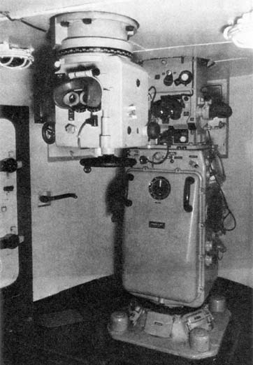
Deck Motion. Deck motion due to ship roll (rocking from side to side), pitch (rocking from bow to stern), and yaw (rocking around the vertical axis of the ship) from wind and waves were also well understood, and methods for compensating for deck motion began to be developed as early as 1898. Hydraulic machinery made it possible to continuously aim heavy guns, and gyroscopes helped automate the process. The Mark 32 director (shown above, left) provided a stable vertical for compensating for ship motion. The view of an interior of a Mark 6 (above, right) shows the gyroscope providing a stable element.
Determining Bearing and Range. Obtaining an accurate bearing was a straightforward matter of providing the fire control party with telescopic sights, except under conditions of poor visibility, when fire control radar became increasingly important. Range was typically provided by optical range finders early in the war and by fire control radar as this became available.
Optical range finders were either coincidence or stereoscopic range finders. Both used large telescopes or prisms at opposite ends of a long crossbar. In a coincidence range finder, the images from the two prisms were combined in a single eyepiece, but matched exactly only when the observer adjusted the range finder to the exact range to target.
Coincidence range finders came in two variants. The older versions showed the image from one telescope in the upper half of the field of view and from the other telescope in the lower half. The observer selected sharp vertical features in the images, such as masts, and adjusted the range until the features were continuous across the boundary between images:
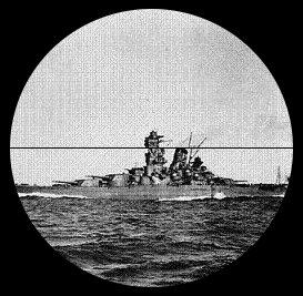
Later, rangefinders were developed that inverted the lower image, which was thought to make finding the coincidence easier.
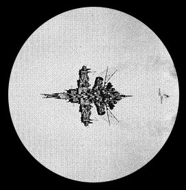
Stereoscopic rangefinders worked like a pair of binoculars, with two eyepieces. The observer's eyes and brain brought the images into coincidence, and range was obtained using a set of marks in each eyepiece that were adjusted until they appeared to be at exactly the same range as the target. The U.S. Navy concluded in 1941 that there was little to choose between the two kinds of range finders.

Rangefinders were best located high in the ship, but the Americans also installed rangefinders in main gun turrets, where they benefited from the protection of the heavy turret armor. These were known as "battle rangefinders".
Correction. There was always some systematic error in an initial fire control solution, no matter how good the data fed to the fire control computer, due to variable atmospheric conditions, gun wear, slight miscalibration of the equipment, or other subtle causes. Thus, the first salvo fired at the target was very likely to miss. Based on which direction the shells missed, the fire control solution was adjusted to bring the next salvo closer to the target. This was known as searching the target area.
Shells that actually hit were very difficult to observe, and those that went over the target were also not easily observed except by spotting aircraft. As a result, the seemingly sensible approach of firing one or two shells and saving the full salvos until the fire control solution was adjusted onto the target was not actually very practical. However, elaborate schemes were worked out to make the most of a single salvo or a set of salvos from several ships concentrating their fire on a single target. The British favored the ladder system, in which several salvos were fired at slightly different ranges to quickly determine the correct range.The Americans, who anticipated fighting in more placid seas, developed instruments to calculate the range error by measuring the angle between the target waterline and the shell splash. However, by the time of the Pacific War, the British had worked out four standard salvo groups. These were a deflection group to find or regain bearing, a ladder group to find or regain range, a zigzag group to rapidly refine a good target solution, and a rapid group to exploit a refined fire solution. The first three groups used two or three salvos, with the third salvo canceled if the first two were far off target, while the rapid group consisted of four salvos.
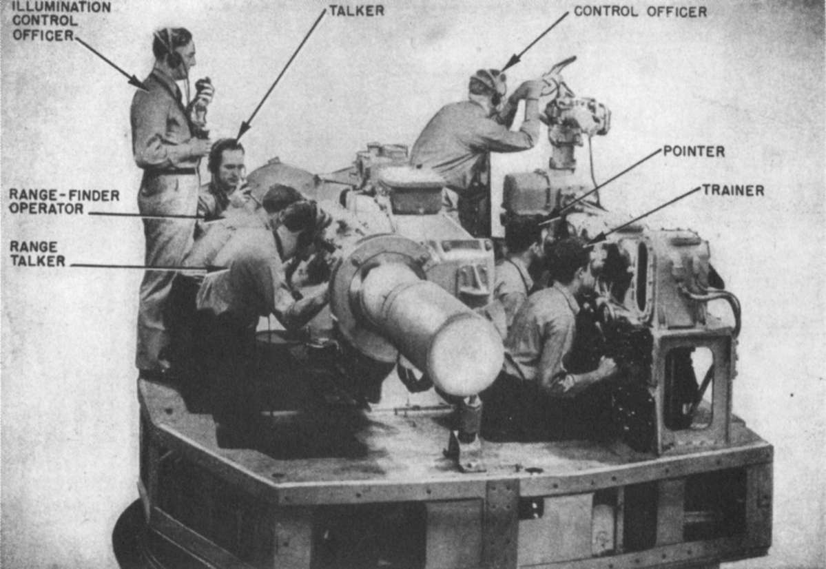
Salvo fire required that all the guns firing the salvo be controlled from a central location, rather than from the individual guns. This was done from a director, which was an observation point high in the ship from which all the guns in a salvo could be fired electrically using a master switch. It was only natural that the director should also include the various sighting telescopes, rangefinders, and other instruments used to collect data for fire control. The British attempted to include early fire control computers in the director itself, and this continued to be the practice with directors for smaller warships, such as the U.S. Mark 18 8" cruiser gun director, or for secondary batteries on larger warships. However, the fire control computers and their operators for the main batteries of cruisers and battleships were too bulky to be included in the director, and they were kept in a separate plotting room within the armored citadel of the ship. This also protected the fire control computers from enemy fire. The directors themselves could not be heavily protected, since they were high in the ship and needed a clear view of the outside world, but large warships were equipped with more than one director so that, if one was destroyed by enemy fire, another could take over.
(Primary source:http://pwencycl.kgbudge.com/F/i/Fire_Control.htm)
This wish goes hand in hand with a wish to model a U.S., Japanese, British and German battleships (and cruisers, perhaps). Carriers for the Japanese and British are a separate but related wish.
Lets attract more WWII surface fleet fans to AH.


