OK, since the bet didn't go through, I guess now I will go through my reasoning. (Altough I'm still willing to take the bet!

)
Here is a graph of a NACA 6-series airfoil, actual test data. The P-51 wing is based on a 6-series airfoil. So while I didn't have the data for the actual P-51 itself (although Pyro provided it -- thank you, Pyro), I figured this would be quite close.
From Aerodynamics, Aeronautics, and Flight Mechanics, by McCormick, p. 69:
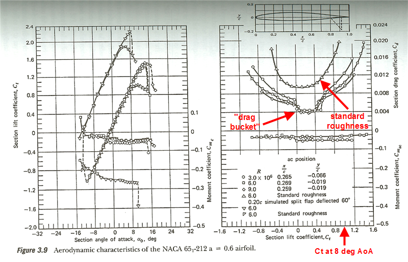
An 8 degree angle of attack of the airfoil (which is a 7 degree angle of attack of the P-51, since wings are mounted with an angle of incedence at root of about 1 degree, so I could really be looking at a 9 degree AoA for the airfoil, but let's use 8 for sake of argument) equates to a Ct of about 1.0.
At a Ct of about 1.0, clearly the drag is higher than at an AoA of zero degrees. This is true both for the "ideal condition" airfoils (very clean, no scratches, no dirt etc.) and certainly for the airfoil with "standard roughness" (just painted -- still no bugs, dents, scratches, etc.). Note two things. First is that "ideal condition" airfoil has the so called "drag bucket," which is the low-drag, laminar flow characteristic Chalenge was correctly indicating in principle, but it is not close to encompassing 8 degrees AoA -- it goes out to only about 2-4 degrees AoA. Second is that "standard roughness" totally eliminates all of that, and you have the more-typical parabolic shape to Cd vs. Ct, where you are quite guaranteed (as Stoney was pointing out from the usual modelling equations) to have higher Cd at a higher Ct.


