lol
The P-61 was used in quite a few missions day also, it was just made as a night fighter.
Usually helps if you add some info on it though, so here's some...
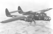
The Northrop P-61 Black Widow was an all-metal, twin-engine, twin-boom, monoplane night fighter and night intruder aircraft flown by the United States Army Air Forces during World War II. It was the only Allied purpose-built aircraft to serve as a radar-equipped night fighter
Changes to the plan
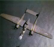
The P-61's upper turret is visible on the fuselage between the wings.Some alternative design features were investigated before finalization. Among them were conversion to a single vertical stabilizer/rudder and the shifting of the nose and tail gun turrets to the top and bottom of the fuselage along with the incorporation of a second gunner.
Late in November 1940, Jack Northrop returned to the crew of three and twin tail/rudder assembly. To meet USAAC's request for more firepower, designers abandoned the ventral turret and mounted four 20 mm Hispano M2 cannons in the wings. As the design evolved, the cannons were subsequently repositioned in the belly of the airplane. The P-61 therefore became one of the few U.S.-designed fighter aircraft to have 20 mm cannons as factory-standard in WWII. Others were the P-38, the F4U-1C (a limited-production Corsair sub-variant), and the A-36 Apache dive-bomber (an early form of the P-51 Mustang). While some F6Fs and repossessed British lend-lease P-39s (renamed as P-400s) were also fitted with 20 mm cannons, it was not standard practice.
Northrop Specification 8A was formally submitted to Army Air Material Command at Wright Field, on December 5, 1940. Following a few small changes, Northrop's NS-8A fulfilled all USAAC requirements, and the Air Corps issued Northrop a Letter of Authority For Purchase on December 17. A contract for two prototypes and two scale models to be used for wind tunnel testing, (costs not to exceed $1,367,000), was awarded on 10 January 1941. Northrop Specification 8A became, by designation of the Department of Defense, the XP-61.
Physical characteristics
The P-61 featured a crew of three: pilot, gunner, and radar operator. It was armed with four 20 mm Hispano M2 forward firing cannons mounted in the lower fuselage, and four Browning M2 .50 cal (12.7 mm) machine guns lined up horizontally with the two middle guns slightly offset upwards in a remotely-aimed turret, dorsally mounted. The turret was driven by the General Electric GE2CFR12A3 gyroscopic fire control computer, and could be directed by either the gunner or radar operator, who both had the aiming control and gyroscopic collimator sight assembly posts attached to their swiveling seats.
The two Pratt & Whitney R2800-25S Double Wasp radial engines were each mounted approximately one-sixth out on the wing's span. Two-stage, two-speed mechanical superchargers were fitted. In an effort to save space and weight, no turbo-superchargers were fitted, despite the expected 50 mph (80 km/h) top speed and 10,000 ft operational ceiling increases.
Each engine cowling and nacelle drew back into tail booms that terminated upwards in large vertical stabilizers and their component rudders, each of a shape similar to a rounded right triangle. The leading edge of each vertical stabilizer was faired smoothly from the surface of the tail boom upwards, swept back to 37 degrees. The horizontal stabilizer extended between the inner surfaces of the two vertical stabilizers, and was approximately three-quarters the chord of the wing root, including the elevator. The elevator spanned approximately one third of the horizontal stabilizer's width, and in overhead plan view, angled inwards in the horizontal from both corners of leading edge towards the trailing edge approximately 15 degrees, forming the elevator into a wide, short trapezoid. The horizontal stabilizer and elevator assembly possessed a subtle airfoil cross-section.
The engines and nacelles were outboard of the wing root and a short "shoulder" section of the wing that possessed a four degrees of dihedral, and were followed by the remainder of the wing which had a dihedral of two degrees. The leading edge of the wing was straight and perpendicular to the aircraft's centerline. The trailing edge was straight and parallel to the leading edge in the shoulder, and tapered forward 15 degrees outboard of the nacelle. Leading edge updraft carburetor intakes were present on the wing shoulder and the root of the outer wing, with a few inches of separation from the engine nacelle itself. They were very similar in appearance to those on the F4U Corsairthin horizontal rectangles with the ends rounded out to nearly a half-circle, with multiple vertical vanes inside to direct the airstream properly.
The P-61 did not have ailerons. Aside from the full-span retractable "Zap flaps", all control of the aircraft about the roll axis was maintained through the use of curved, tapered spoilerons, of approximately ten feet in length and six inches in width (in overhead plan view) each. They were located outboard of the outer edge of each nacelle in overhead plan view, approximately one-quarter the length of the outer wing (the section of wing outboard of the edge of each nacelle furthest from the aircraft's centerline) and offset towards the wing leading edge approximately one third the wing's chord from the trailing edge, running towards the wing-tip approximately half the length of the outer wing. Operation was as follows: the spoileron in the inside wing rotated out of the wing's upper surface into the airstream, disrupting the effect of Bernoulli's principle and reducing lift over that wing, causing it to drop.
Beneath the forward crew compartment was the nose gear wheel well, through which the pilot and gunner entered and exited the aircraft. The forward gear leg retracted to the rear, up against a contoured cover that when closed for flight formed part of the cockpit floor; the gear would not have space to retract with it open. The oleo scissor faced forwards. The nosewheel was centered, with the strut forking to the aircraft's left. The nosewheel was approximately three-fourths the diameter of the main wheels. Nose gear doors were two pieces, split evenly longitudinally, and hinged at each outboard edge.
The center of the gondola housed the main wing spar, fuel storage, fuel piping and control mechanisms, control surface cable sections, propeller and engine controls, and radio/IFF (Identification Friend or Foe) /communications equipment, but was predominantly occupied by the top turret mounting ring, rotation and elevation mechanisms, ammunition storage for the turret's four Browning M2 machine guns, the GE2CFR12A3 gyroscopic fire control computer, and linkages to the gunner and radar operator's turret control columns, forward and aft, respectively.
The cross-section of the gondola, front to back, was generally rectangular, vertically oriented. The tip of the nose was very rounded, merging quickly to a rectangular cross-section that tapered slightly towards the bottom. This cross-section lost its taper but became clearly rounded at the bottom moving back through the forward crew compartment and nose gear well. Height increased at both steps in the forward canopy, with the second step being flush with the top of the aircraft (not counting the spinal gun turret). At the rear of the forward crew compartment, the cross-section's bottom bulged downwards considerably and continued to do so until just past the midpoint between the rear of the forward crew compartment and the front of the rear crew compartment, where the lower curvature began to recede. Beginning at the front of the rear crew compartment, the top of the cross-section began to taper increasingly inwards above the aircraft's center of gravity when progressing towards the rear of the gondola. The cross-section rounded out considerably by the downward step in the rear canopy, and rapidly became a straight-sided oval, shrinking and terminating in the tip of the blown-Plexiglas "cone" described above.
The cross-section of the nacelles was essentially circular throughout, growing then diminishing in size when moving from the engine cowlings past the wing and gear bay, towards the tail booms and the vertical stabilizers. A bulge on the top of the wing maintained the circular cross-section as the nacelles intersected the wing. The cross-section became slightly egg-shaped around the main gear bays, larger at the bottom but still round. An oblong bulge on the bottom of the main gear doors, oriented longitudinally, accommodated the main wheels when the gear was retracted.
Wing tips, wing-to-nacelle joints, tips and edge of stabilizers and control surfaces (excluding the horizontal stabilizer and elevator) were all smoothly rounded, blended or filleted. The overall design was exceptionally clean and fluid as the aircraft possessed very few sharp corners or edges.