Author Topic: Discuss.  (Read 6924 times)

Offline Charge

  • Gold Member
  • *****
  • Posts: 3414
Discuss.
« Reply #30 on: December 07, 2007, 09:56:04 AM »
Elliptical planform and its advantages are not BS, it is just more costly and time consuming to manufacure and the benefits are not always seen worth it.

Elliptical planform itself did not make the qualities of Spitfire but because of the size of the wing every measure had to be taken to minimize drag and making it elliptic was one of them. The wash-out did not have too radical effects on its lift distribution IMO, but it did make it worse but still it was better than those of P51 and FW190 as can be seen in Davis Lednicher's report. That report considers only one state of flight and AoA, the graphs would be different with more AoA so the graph is not a general description of its qualities but a snapshot of one situation -probably at 0 DEG AoA.

The bad feature was indeed the stall characteristics and washout helped the pilot so that the buffeting of the root of the wing at stall warned to pilot to tighten the turn so that the tip would not stall as well. But if that happened the stall was probably quite sudden and I have understood that Spit went easily into flat spin but that has more to do with lift center relation to CoG and their shifting due to centrifugal force more than some negative feature of an elliptic planform.

-C+
"When you wish upon a falling star, your dreams can come true. Unless it's really a giant meteor hurtling to the earth which will destroy all life. Then you're pretty much screwed no matter what you wish for. Unless of course, it's death by meteorite."

Offline Stoney74

  • Silver Member
  • ****
  • Posts: 1439
Discuss.
« Reply #31 on: December 07, 2007, 08:14:17 PM »
Quote
Originally posted by Charge
...as can be seen in Davis Lednicher's report. That report considers only one state of flight and AoA...


Do you have a link or copy of this?  I tried to find it on the web with no luck.  Furthermore, I can't find a credible source that actually discusses the washout designed into the Spitfire wing.

Quote
The bad feature was indeed the stall characteristics and washout helped the pilot so that the buffeting of the root of the wing at stall warned to pilot to tighten the turn so that the tip would not stall as well.

-C+ [/B]


Given the wing geometry used by all WWII fighters, I believe they were all doomed to have poor stall characteristics, regardless of the band aids of washout, slats, etc.  Between poor airfoil section stall characteristics, coupled with thickness taper, coupled with planform taper, (none of which could have been foreseen given the knowledge base at the time) and massive amounts of torque from those monster engines all combined to make stick and rudder skills a most valuable commodity.

Offline Stoney74

  • Silver Member
  • ****
  • Posts: 1439
Discuss.
« Reply #32 on: December 07, 2007, 09:27:31 PM »
Ok, here is an example of why a thinner wing may not be "better" than a thicker wing.  I have to admit that this airfoil did not turn out to be as good an example as I thought it would.  I'll look for a better one later...

I ran both the NACA 23015 and the NACA 23009 through XFOIL96.  XFOIL is an airfoil analysis program.  XFOIL is not in total agreement with the NACA airfoil wind tunnel test data shown in NACA Report 824, but the comparison is useful regardless.  For my test runs, the Reynolds number was set at 3.0E6 (or 3,000,000) and the Mach at .17 which are the same conditions used by NACA to develop the data for Report 824.  These are NOT similar to the conditions that an actual aircraft using this airfoil during WWII would have--I merely used them to set up the same conditions NACA used.
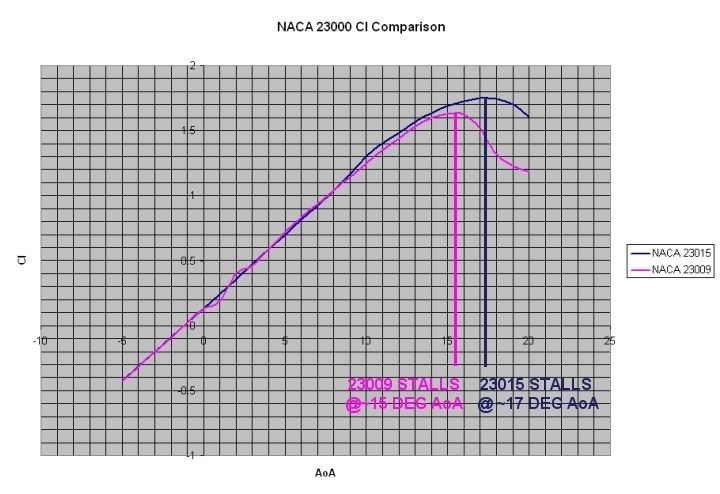


In this image, you'll notice that the thinner airfoil (NACA 23009) a 9% thickness airfoil, stalls earlier than the thicker airfoil (NACA 23015).  Also note that beginning at about 9 degrees AoA, the 23015 produces more lift at the same AoA, all the way to the stall.
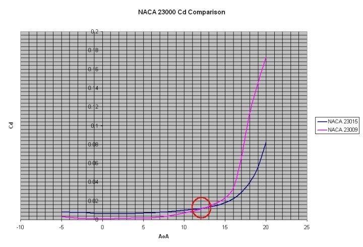


In this image, you'll notice that the thinner airfoil creates less drag at low AoA, but as the AoA increases, the difference between the two decreases, and by 12 degrees AoA, the thinner wing actually produces more drag at the same AoA than the thicker wing.

I didn't take the time to do a lift/drag curve for both aircraft, but you could see that at certain portions of the flight envelope, the thicker airfoil section can be more "aerodynamic" than the thinner airfoil section.  

Another interesting illustration here is the impact of airfoil thickness on tip stalls.  Almost all WWII fighter aircraft used thickness taper, where the airfoil thickness at the wing tip was thinner than at the root.  The NACA 23012 root, 23009 tip was a popular combination on many WWII aircraft.  You can see from this comparison, that as the wing approached the stall condition, the wing tip would stall much earlier than the root.  When this happens, the engine torque rolls the aircraft quickly over onto its back, aka a snap roll.  

I'll see if I can't follow up on this later...
« Last Edit: December 07, 2007, 09:33:27 PM by Stoney74 »

Offline dtango

  • Silver Member
  • ****
  • Posts: 1702
Discuss.
« Reply #33 on: December 07, 2007, 11:11:42 PM »
Charge:  very much agree with your comments on the elliptical wing.  Unfortunately there's too much mis-information out there on the topic.

Stoney:  I have a pdf copy of Dave Lednicer's report that he graciously sent to me.  PM me with your email and I'll send it along to you.

Nice work with xfoil :).  I'll have to talk to you about how you got it working.  When I looked at it a couple of years ago it seemed too much effort to get working on a PC.

Tango, XO
412th FS Braunco Mustangs
Tango / Tango412 412th FS Braunco Mustangs
"At times it seems like people think they can chuck bunch of anecdotes into some converter which comes up with the flight model." (Wmaker)

Offline SgtPappy

  • Silver Member
  • ****
  • Posts: 1174
Discuss.
« Reply #34 on: December 07, 2007, 11:15:46 PM »
That's a good example, Stoney. Don't worry about being blunt, I'm fine and the world isn't going to worry about being polite to people anyway haha.

Anyway, do you have aircraft examples of those airfoils? Just so I can get a better idea of how they worked.

Charge,
I now know the ellipse wasn't fake at all. As Stoney mentioned, the reports made on the elliptical wing were rather questionable and I, in attempt to understand those reports, found those methods questionable as well.
I am a Spitdweeb

"Oh I have slipped the surly bonds of earth... Put out my hand and touched the face of God." -J.G. Magee Jr.

Offline Stoney74

  • Silver Member
  • ****
  • Posts: 1439
Discuss.
« Reply #35 on: December 07, 2007, 11:36:12 PM »
Quote
Originally posted by SgtPappy
Anyway, do you have aircraft examples of those airfoils? Just so I can get a better idea of how they worked.


You mean like specific airfoils for specific airplanes?  Or 3D analyses of wings using specific airfoils?

Offline Charge

  • Gold Member
  • *****
  • Posts: 3414
Discuss.
« Reply #36 on: December 08, 2007, 02:28:14 PM »
"Given the wing geometry used by all WWII fighters, I believe they were all doomed to have poor stall characteristics, regardless of the band aids of washout, slats, etc. Between poor airfoil section stall characteristics, coupled with thickness taper, coupled with planform taper, (none of which could have been foreseen given the knowledge base at the time) and massive amounts of torque from those monster engines all combined to make stick and rudder skills a most valuable commodity."

I once saw a pressure distribution chart for a normal straight leading edge wing and that chart pretty much explained why the arched leading edge of Spitfire is beneficial dragwise. I have often searched that article but never found it again. It could have been one of those NACA articles though...

I'm not sure but I think that the stall problem with the elliptic planform may be due to that arched leading edge causing an even pressure distribution along the wingspan (meaning an even forming of drag) but at the same time causing the lift to be lost all at once if the max permissible AoA is exceeded, so the washout is indeed the only means of making the impeding stall somewhat predictable, and according to what I have read it worked if the stall was approached somewhat carefully. So the tipstalling charcteristics of a normal tapered wing is probably not caused by planform itself but due to fact that the thinner wing section stalls first, but the tapering may delay the stall to a point where the whole wing stalls at the same time.

(I'm talking about planform taper, not profile taper.)

If you compare the commonly used profiles you notice that while the root section profile of 109 (F,G,K) is quite common 14-15% thickness the tip profile is thicker 11% than those of other design's typical 9%. Probably good for stall characteristics but bad for drag unless the planform is kept quite thin at the tip.

This means that accompanied with slats the 109 could probably "ride the stall" for quite long up to significant AoAs (20-25deg?) but only the tips of the wing providing lift in the end as the stalling would reduce the positive wing area as the AoA would increase. I have no idea what is actually the value of that amount of lift in maneuvers and in fact it may well be that 109 ran out of lift before the wing would stall, the remaining effective wing area not able to support the weight of the a/c. (This would suggest that the situation would be different in high speed, but the stalling characteristics would be too...)

Previously I had made a general assumption that the slats would open only at approach of stall but that is not the case as was evident by the flying video of Black 6 where you could see the slats slightly moving in and out even in slow level flight. That didn't make sense to me so I concluded that these matters are not always as straight forward as they may seem.

-C+
"When you wish upon a falling star, your dreams can come true. Unless it's really a giant meteor hurtling to the earth which will destroy all life. Then you're pretty much screwed no matter what you wish for. Unless of course, it's death by meteorite."

Offline Stoney74

  • Silver Member
  • ****
  • Posts: 1439
Discuss.
« Reply #37 on: December 09, 2007, 04:19:29 AM »
Quote
Originally posted by Charge
I'm not sure but I think that the stall problem with the elliptic planform may be due to that arched leading edge causing an even pressure distribution along the wingspan (meaning an even forming of drag) but at the same time causing the lift to be lost all at once if the max permissible AoA is exceeded, so the washout is indeed the only means of making the impeding stall somewhat predictable, and according to what I have read it worked if the stall was approached somewhat carefully. So the tipstalling charcteristics of a normal tapered wing is probably not caused by planform itself but due to fact that the thinner wing section stalls first, but the tapering may delay the stall to a point where the whole wing stalls at the same time.

(I'm talking about planform taper, not profile taper.)-C+


Well, the problem with planform taper is that the Reynolds number at the tip will be much lower than the Reynolds number at the root.  So, in addition to a thinner airfoil section (with its reduced Clmax/quicker stall), the reduced chord at the tip has a lower Rn, which also reduces Clmax.  There are acceptable amounts of taper, but any taper contributes to a greater potential for tip stall.  

I'll do a Reynolds number comparison for the Spit airfoil to demonstrate, and post it.

Offline Stoney74

  • Silver Member
  • ****
  • Posts: 1439
Discuss.
« Reply #38 on: December 09, 2007, 02:08:58 PM »
Ok, here we go.  


This chart shows the same NACA 2209 airfoil used on the Spitfire wing tip.  Although the Spit used a 2209.5, XFOIL doesn't like fractional thicknesses, and I figured the difference would be negligible.  Regardless, you can see that the same airfoil section thickness stalls earlier at lower Reynolds numbers than at higher Reynolds numbers.  This illustrates the effect planform taper has on tip stall.  If velocity, density, etc. are held constant, and the wing tip chord is the only variable, the difference shown here is a wingtip of shorter chord (lower Rn) versus a wingtip of longer chord (higher Rn)

So, both airfoil thickness taper and planform taper contribute to a higher potential for tip stall.  You begin to get an idea why almost all WWII fighters display such nasty tip stall characteristics.  That's not to say that either don't have their uses, but in the ongoing tradeoff that is aircraft design, you could make an argument that many non-combat losses of aircraft may have been avoided by changing the wing geometry that was used by both Axis and Allied manufacturers.  For example, perhaps the Corsair would have had more benign slow flight characteristics had there not been any airfoil thickness taper.  And, perhaps the Spit would not have needed any washout (which increased drag) had there not been such extreme planform taper.
« Last Edit: December 09, 2007, 02:19:32 PM by Stoney74 »

Offline Stoney74

  • Silver Member
  • ****
  • Posts: 1439
Discuss.
« Reply #39 on: December 11, 2007, 07:05:51 PM »
Sgt Pappy/Motherland,

A good general discussion of wing planform, taper, etc. and its effect on wing efficiency located here

Offline gripen

  • Silver Member
  • ****
  • Posts: 1914
Discuss.
« Reply #40 on: December 17, 2007, 04:36:55 AM »
Quote
Originally posted by Stoney74
It's not so much that the elliptical wing theory is B.S. as it is that NACA used some questionable methods to arrive at that conclusion (source Ribblet GA Airfoils).


Originally the elliptical lift distribution was introduce after WWI by a German aerodynamicist L. Prandtl as part of his lifting line theory. The idea was that elliptical planform offers constant downwash along the wingspan and therefore minimizes induced drag. A bit later (1926) Glauert introduced calculation methods to expand the theory to the other planforms. Notable thing is that Prandtl and Glauert dealed only with induced part of the drag (ie only directly lift related) so couple years later (1933) W.B. Oswald at NACA introduced his methods to calculate aircraft performance and he lumped all induced and parasitic drag (due to lift) factors together creating his  now famous e factor.

Offline Stoney74

  • Silver Member
  • ****
  • Posts: 1439
Discuss.
« Reply #41 on: December 17, 2007, 11:21:56 PM »
Quote
Originally posted by gripen
...couple years later (1933) W.B. Oswald at NACA introduced his methods to calculate aircraft performance and he lumped all induced and parasitic drag (due to lift) factors together creating his  now famous e factor.


In NACA Report 627, NACA made the case for an elliptical planform as the ideal planform.  It tested 22 different combinations of aspect ratio, planform taper, thickness taper, etc. and tested their stall characteristics, among other properties.  

The following is an excerpt from "GA Airfoils" by Harry Riblet (page 100):  "One final comment is needed regarding NACA sample #22, with the elliptical planform.  This specimen has the highest Clmax (1.81) of any tested, and is accordingly often cited as proof of the "inherent superiority" of the elliptical planform over uniformly tapered planforms.  Note, however, that this specimen enjoys two distinct advantages over the other specimens--it has a unique high-lift section (4412), and in addition it has the same percent thickness at the root and tip, 12%, which is, as we have seen, the optimum thickness in terms of best L/D.  In view of this, we wonder if the legendary mystique of the elliptical planform is justified."

The point he's making here, is that from a purely scientific standpoint, the research is flawed.  NACA did not take, for example, the same planform, airfoil, planform taper, and thickness taper and then only adjust one of these variables at a time.  Instead, they came up with 22 unique combinations and compared them to each other.

Whether or not a properly configured elliptical planform is the best ideal configuration, NACA's research, in retrospect, by itself does not provide a compelling argument for an elliptical planform.  The argument is that a uniformly planform-tapered wing can realize elliptical lift distribution just as well as a wing with an elliptical planform.

Too many folks confuse the idea of elliptical lift distribution with elliptical planforms.  One can exist independent of the other.

Offline gripen

  • Silver Member
  • ****
  • Posts: 1914
Discuss.
« Reply #42 on: December 18, 2007, 04:59:09 AM »
Quote
Originally posted by Stoney74
In NACA Report 627, NACA made the case for an elliptical planform as the ideal planform.  It tested 22 different combinations of aspect ratio, planform taper, thickness taper, etc. and tested their stall characteristics, among other properties.


Nope, elliptical planform was introduced as a special case of elliptical lift distribution by Prandtl (1919) and Glauert developed the theory further. Following is a quote from Glauert's work (H. Glauert: "The elements of Aerofoil and Airscrew Theory." University Press Cambridge 1926, p. 143-144):

"The elliptic distribution of circulation or lift across the span of an aerofoil is important, firstly because it leads to minimum possible induced drag for given total lift, and secondly because the load grading curves of most aerofoils of conventional shape do not differ greatly from the elliptic form. The results deduced from hypothesis of elliptic loading are therefore the best which can possibly occur and are also a good first approximation to those actually obtained...

[formulas and discussion for mathematical proof omitted]

Hence the lift coefficient also will have the same value for all sections of the aerofoil. But the circulation... varies elliptically across the span, so also will the chord. Thus the elliptic loading will be obtained from a monoplane aerofoil of elliptic plan form and constant angle of incidence....

Elliptic loading across the span can also be obtained from aerofoils of other plan form by suitable variation of the angle of incidence across the span, but any such twisted aerofoil will give the elliptic loading for one attitude only, since the necessary angle of twist depends on the mean angle of incidence of the aerofoil.
"

Note that  couple pages later Glauert gives also formulas for tapered wings as well.

Quote
Originally posted by Stoney74
The point he's making here, is that from a purely scientific standpoint, the research is flawed.  NACA did not take, for example, the same planform, airfoil, planform taper, and thickness taper and then only adjust one of these variables at a time.  Instead, they came up with 22 unique combinations and compared them to each other.


While Riblet is obviously right in his critics, the elliptical planform was allready invented by Prandtl nearly 20 years earlier.

Note also that the NACA 627 test results contain induced as well as parasitic drag of the wing so they did not exactly measure the effects of planform to induced drag.

BTW we use quite back wards pointed wing tips in the fast RC-gliders to minimize wing tip vortices (idea originally invented by S. Hoerner and tested in the Bf 109 during war). Here is a drawing showing high performance "Raketenwurm".

Quote
Originally posted by Stoney74
Too many folks confuse the idea of elliptical lift distribution with elliptical planforms.  One can exist independent of the other.


That was invented by Glauert as continuation to Prandtl's work some 10 years before the NACA 627 as pointed out above.

Notable thing is that similar ideas as Prandtl's theory were presented as early as 1907 by F. Lanchester so overall it's difficult to say who invented what and when.

Offline Stoney74

  • Silver Member
  • ****
  • Posts: 1439
Discuss.
« Reply #43 on: December 18, 2007, 08:15:45 AM »
Quote
Originally posted by gripen
Nope, elliptical planform was introduced as a special case of elliptical lift distribution by Prandtl (1919) and Glauert developed the theory further.


Sorry, I didn't mean to imply that NACA invented the theory of elliptical distribution or the idea of the elliptical planform.  I was simply alluding to their windtunnel research of the topic.  

Good information about Prandtl and Glauert.