This is an update of a tutorial for the new AH III skin file system I originally posted in the beta forum. I've corrected a few things in it that are no longer true.
The current AH II skins system uses image maps to control the diffuse, bump and specular effects for each individual pixel of a skin, with text files to alter other lighting effects globally over the whole skin. When AH III does go live then all skins will be changed to a new system where only image maps are used to control these effects. The AH III skin files will have different names and existing skins will have their files renamed automatically by HTC. Until AH III goes live any skins submissions will use the existing system.
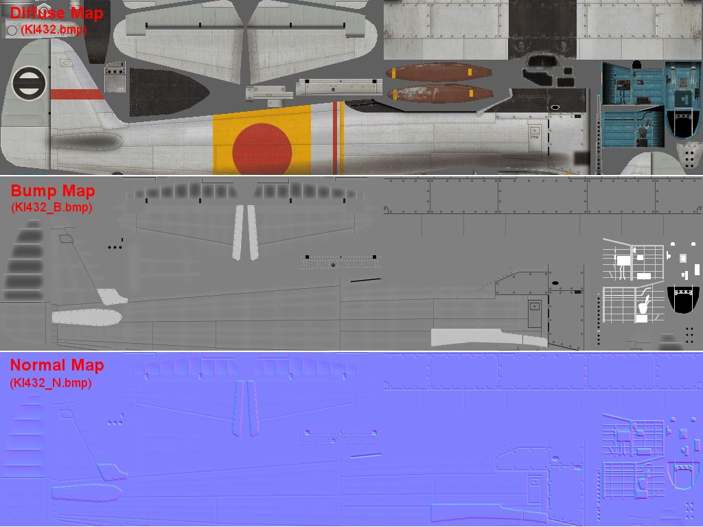
Shown below are six versions of the same section from an existing Ki-43 skin that I have updated to the new AH III format. Some of these are the same as before or just renamed and some are new.
The
Diffuse Map is the basic skin file that all skins share, it is simply a painting of the skin draped over the 3D shape. No changes have been made to this file, even the name stays the same as before. It may be that some skinners will want to reduce or remove some baked-in shading effects from their diffuse maps that can better be done with the other maps.
The
Bump Map from AH II is no longer used for AH III but one is still needed in order to create its replacement, the normal map. On it lighter shades represent raised areas and darker shades lower areas.
The
Normal Map replaces the old AH II bump map. It does the same job of creating fake bumps and dips on the surface of the skin by creating shadows and highlights derived from the position of the sun. A normal map stores information about the relative angle of each pixel to the surface, not just its relative height, so it tends to be a lot more detailed.
For example the bump map image below shows some blurred dips on the fabric control surfaces and blurred bumps around the rivet lines. However I created these for use with the normal map. On the old bump map blurred shapes like these to have a badly-banded appearance on the skin (put another way, it looks crap). On a normal map however there is much less banding and these effects can give a decent illusion of dips between the underlying structure of the airframe. The blurred white lines are made from a copy of the rivet layer which is then just gaussian blurred by several pixels.
Nvidia make a free normal-generating plug-in that works with Photoshop and Paintshop Pro:-
https://developer.nvidia.com/nvidia-texture-tools-adobe-photoshopThere is also a free normal tool available for Gimp:
http://registry.gimp.org/node/69Some normal software is stand-alone and some can be linked to your graphics editing program as a plug-in that you can access directly through a menu command. Your graphics program's help file should tell you how to set up a plug-in if you don't know how. Before making a normal map you first need to make sure the bump map image you are making it from is in the right format. All the other files listed here are saved as 8-bit bmps (256 colour or greyscale) but the normal-generating software will only work on higher bit rates, 16 or 32-bit. Increasing the bit-rate can easily be done in any graphics program.
Once you activate your normal software it will bring up a window giving numerous display options. On the Nvidia plug-in that I use the only settings I have altered from default are "Invert Y" and "Scale". Invert Y changes the look of the normal file so that it appears light is coming from the top rather than the bottom of the image and this makes the resultant normal image a lot easier to understand. Scale alters the size of the bumps, a bigger number means bigger bumps. You can also reduce the bump sizes by using less extreme shades of grey on your original bump map but generally it is better to use the scale setting.
The
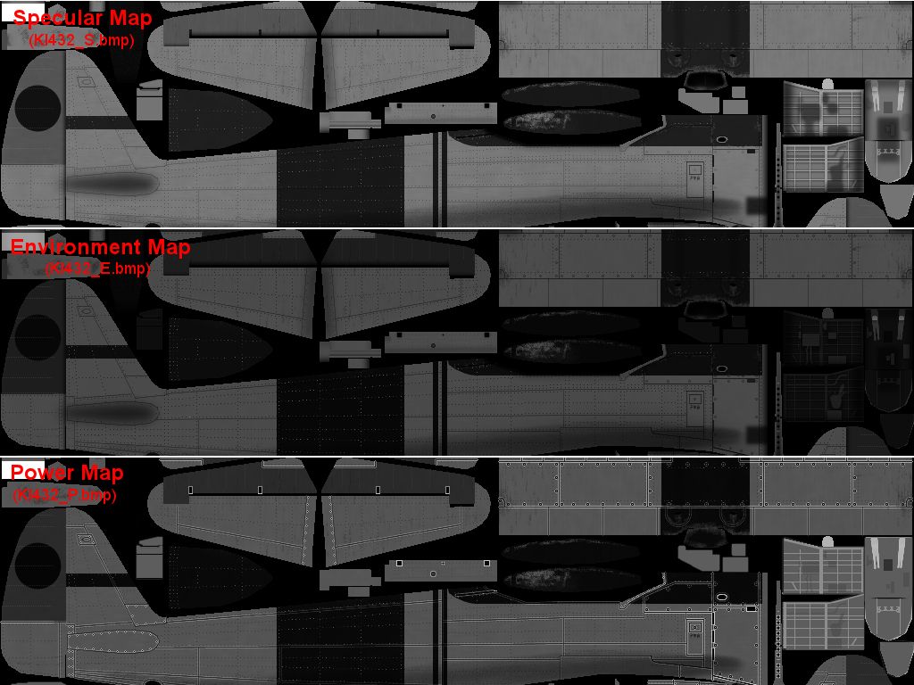
Specular Map is essentially the same as in AH2 but the file's suffix has changed from _B_a to a more logical _S. This file controls how the surface of the skin reflects the sun's rays. Lighter areas are more reflective and darker less. This file makes a big difference to bare metal skins like this Ki-43, the bright reflections on the metal areas and weak ones on the paintwork create a powerful illusion.
The
Environment Map is a new file with an _E suffix. It controls how the skin reflects the sky and land around it. The environment map is easily created from a copy of the specular map and looks quite similar to it. This is because different surfaces tend to reflect both the sun's rays and the environment to a similar degree, i.e metal reflects both types of light better than paint. An area of the environment map that is close to white will give a chrome-like appearance to the skin. While this can look quite pretty my personal view is that this is not very realistic for a WW2 metal finish so I like to dull this effect down. This is why the environment map shades shown below are a bit darker than their specular map equivalents. The only areas that are near-white are glass areas and highly polished inner gear pistons.
The
Power Map is another new file with a _P suffix. It controls how sharp the highlights are on the skin. This is also created from the specular map and also looks similar to it, with sharper highlights shown in lighter shades. It looks similar because shiny surfaces like metal tend to have sharp highlights and matt surfaces like paint or rubber have vague highlights.
There is one different effect that can be added to the power map however. It is possible to make the edges of the panels to either side of panel lines have extra-sharp highlights. On the power map image below you can see I have got lighter lines outlining my panel lines and this is fairly simple to achieve. If you have several panel line layers make copies of each layer and merge these. Call this layer "Merged panel lines". Now make another copy of this layer, call it "Panel line edges" and turn all the lines on it white. Using copy and paste carefully position four copies of the white lines so that each copy is one pixel offset to the top, bottom left and right. What you should end up with is a panel line layer in white but with three pixel thick lines. Next move back to the "Merged panel line" layer, use a select tool to select all the lines, go back to the "Panel line edges" layer and hit the "delete" key. This erases the centres of your three-pixel thick lines, but leaves the outer lines intact. The merged panel line layer can now be deleted. For this bare metal skin I made a second copy of the panel edges layer and put one above the paint layers and one below to create harder edge highlights on the bare metal areas.
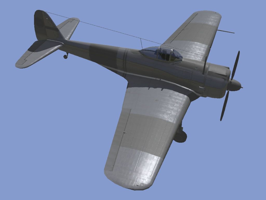
Putting it all together. The alpha skin viewer has a number of new buttons to help skinners work with these new files. These allow the effects of each map to be viewed in isolation, or with all the effects shown together or, as in the "Lighting Only" screenshot below, with all the effects except the diffuse map shown. Here you can see the effects of the normal map, the panel lines scribed into the surface and the structure ripples in the highlights on the wing. Also the specularity, environment and power differences in the reflections between the painted and bare metal areas. The environment effect is displayed best on the side of the fuselage which is bluer on its top half and greener below.
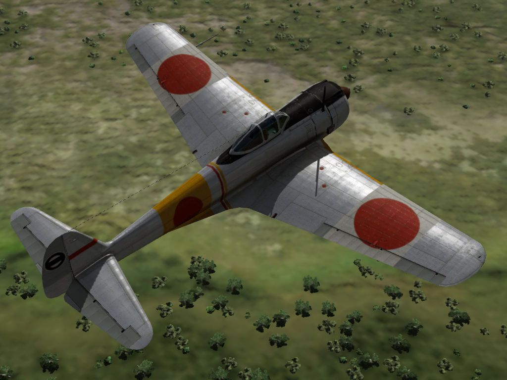
The in-game screenshots shows what it looks like when its all put together.


